LADE
A MOBILE SURFACE LUNAR HABITAT
Project ID


PARTNERS
YEAR
SITE
TYPE
TEAM
ROLE
Alta Scuola Politecnica
Massachussets Institute of Technology
Thales Alenia Space
2021-2022
South Pole, Moon
Multidisciplinary Project
Daniele Florenzano, Michela Botti, Lorenzo Calogero, Ana Carolina Correa Caracas, Alessandro Caruso, Marta Mattioli, Marco Portolani, Angela Rizzo, Giulia Signorotto
Team Lead, Visualizer, Computational Designer, Structural Designer

Project Description
Since Apollo missions, robotic exploration of deep space has seen decades of technological advancement and scientific discoveries. Today, NASA’s Artemis Program is envisioning a plan to drive humanity to live on the Moon. Indeed, the possibility of building a permanent settlement on the Moon is still a major challenge.
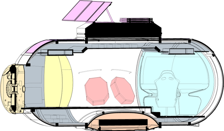
Lunar Architecture Design Exploration (LADE) project’s output is a mobile space architecture system that enables human presence on the Moon, allowing medium to long term missions.
The design workflow for LADE is strictly connected and dependent on the mission definition, payload constraints and mobility requirements of the mobile habitat. These conditions guided the parametric optimization process leading to a final geometrical configuration. The structure has then been optimized and tuned to satisfy the constraints using a data driven approach.


Deployment strategy
In order to maximize the flexibility of the module, as well as reducing to the minimum the payload volume, the module is divided into the pressurized habitable shell and the mobility system of the rocker bogie.
The deployment procedure is composed by 5 steps:
-
The landing phase, where the compacted and detached elements are stored within the lander.
-
The second phase is the Disposition, where the shell, sustained by a rigid support at its bottom, is positioned on the surface along with the rocker bogie structure, still in its compact form
-
The third phase refers to the deployment of the rocker bogie system, where the telescopic legs connected to the differential at the very top of the structures will expand and rotate to reach the correct position for motion
-
The fourth phase is dedicated to the coupling of the structure so that the contact surface of the shell and the rocker bogie match perfectly and allow for connection through a clamping mechanism.
-
The last phase sees the complete module composed by the rocker bogie attached to the habitat space of the shell, ready to leave for the missions.

Module Coupling


